Click on each tab to open for more information. Click tab again to close.
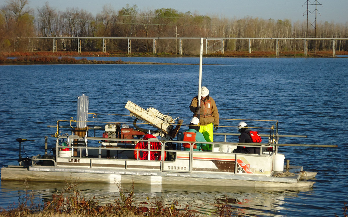
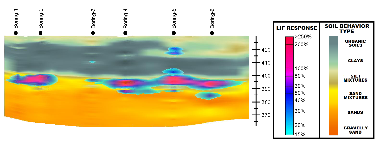
Cone Penetration Testing/Laser Induced Fluorescence (CPT/LIF) application represents an efficient application that combines in-situ geologic and real-time hydrocarbon screening data to evaluate the presence and distribution of light non-aqueous phase liquid (LNAPL) in the stratigraphic environment. The CPT characterizes the soil stratigraphy while LIF identifies the presence of petroleum hydrocarbons.
Key aspects of these investigation methods include:
CPT/MIP application combines in-situ geologic and real-time screening data to evaluate the presence and distribution of dissolved phase volatile organic compounds (VOCs). The MIP technology uses a down-hole sensor mounted on a CPT probe to characterize stratigraphy and to provide continuous in-situ screening for VOCs and detect their relative concentration. The MIP probe heats and volatilizes VOCs in the soil and groundwater, which diffuse across a hydrophobic membrane and are swept by a carrier gas to a series of detectors located in the CPT rig. Typical detectors are photo ionization detector (PID), flame ionization detector (FID), electron capture detector (ECD), and dry electrolytic conductivity detector (DELCD).
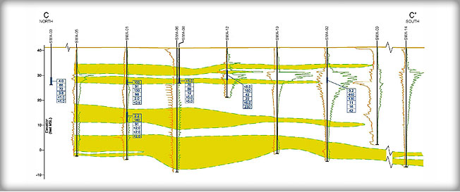
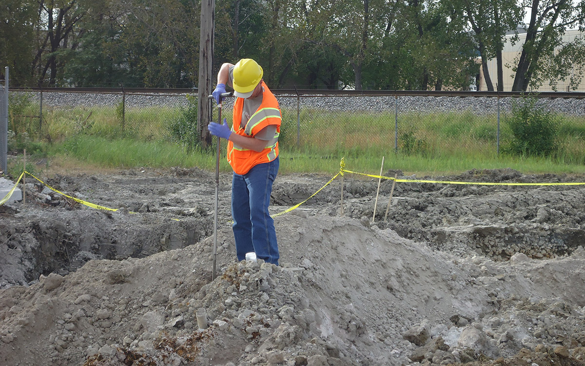
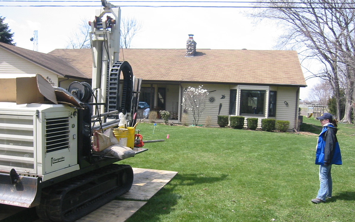
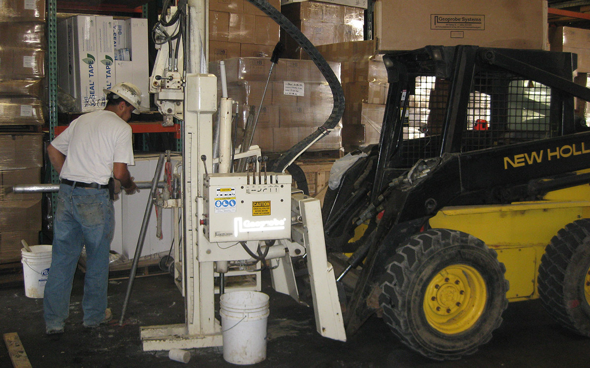
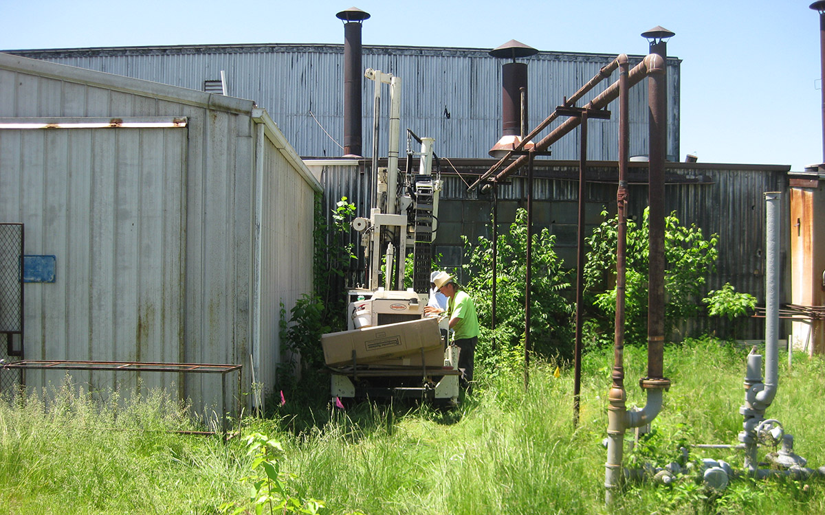
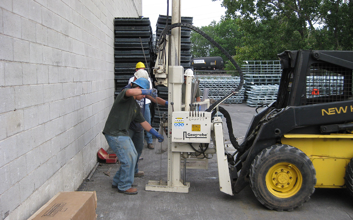
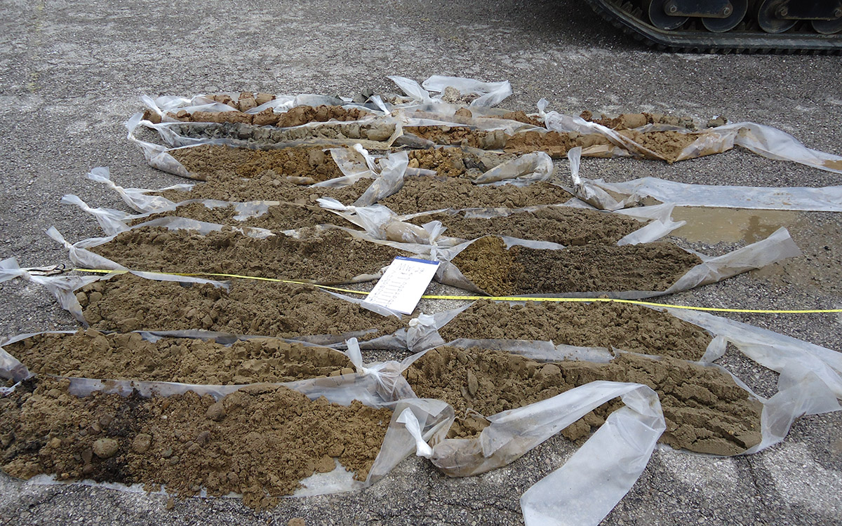
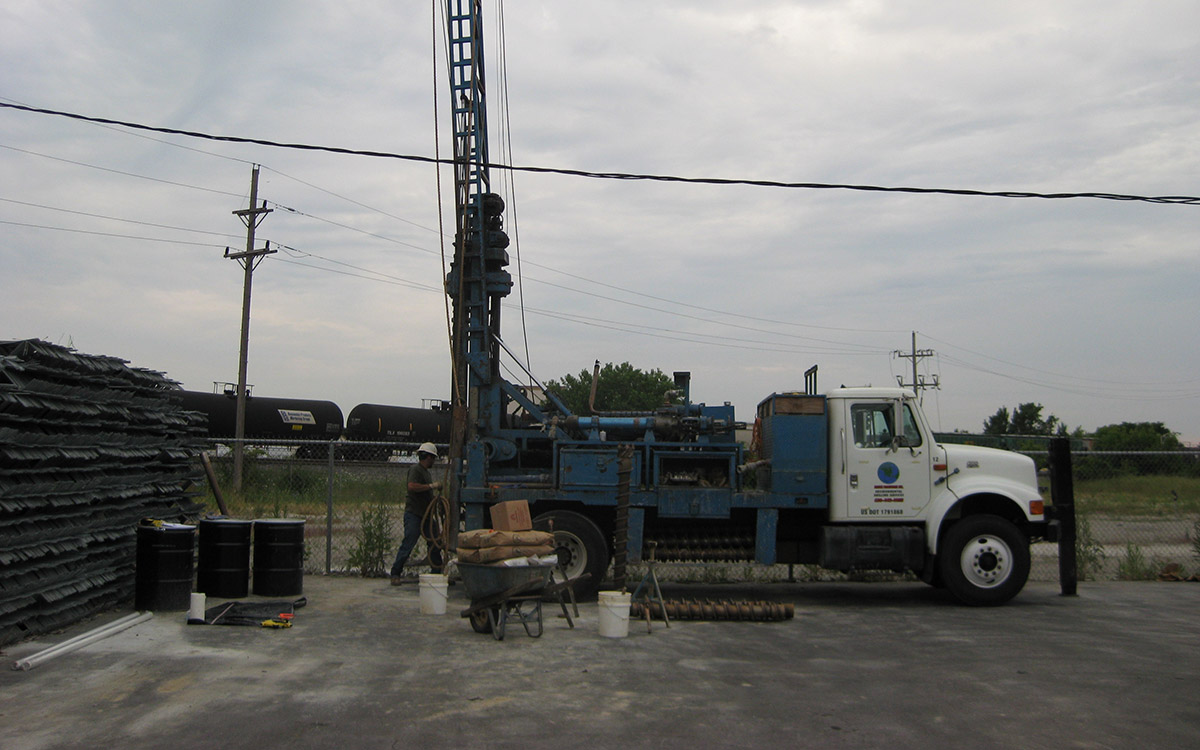
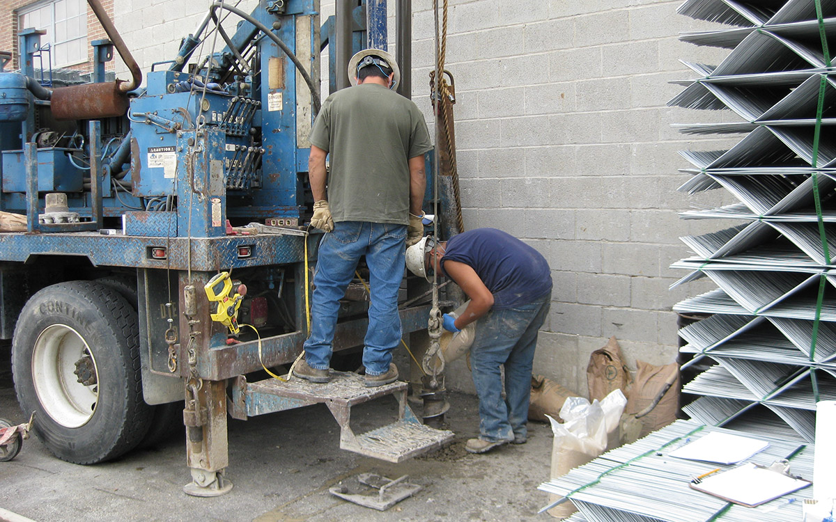
Soil borings are completed in order to collect soil samples for geotechnical or chemical laboratory analysis, classify the soil to determine geological/lithological units, and to better understand the subsurface to aide in exploring contamination boundaries. SMA mostly utilizes the use of direct push/Geoprobe® technology in order to collect soil samples quickly and efficiently with minimal impact to the surrounding area.
Soil samples are classified and logged in the field by Geologist/Environmental Scientists and geotechnical or analytical chemical sampling locations are determined and the samples are collected. The data that is collected from soil borings can then be used to generate geologic cross sections, 2D and 3D models, and analytical tables and figures.
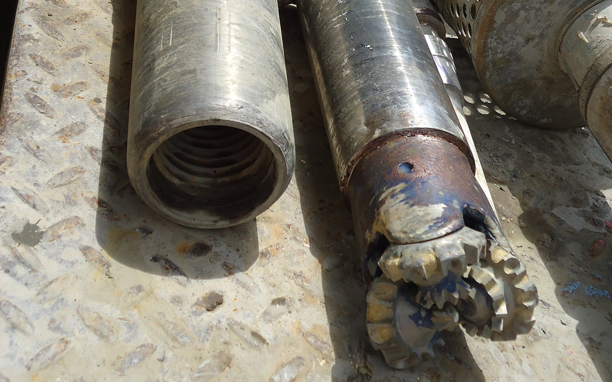
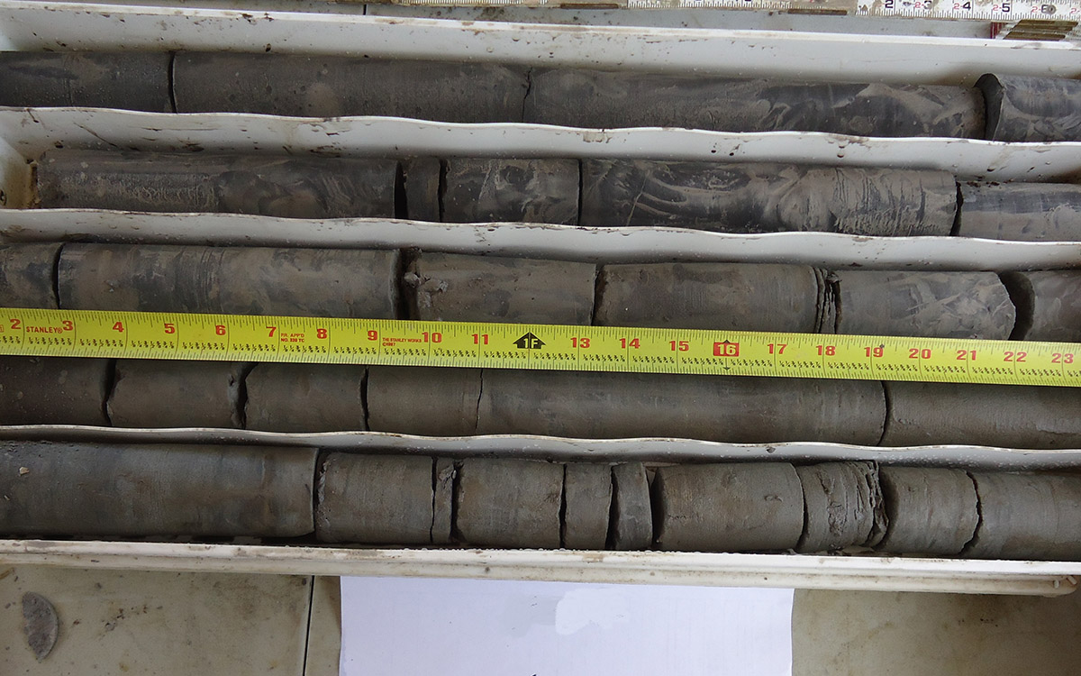
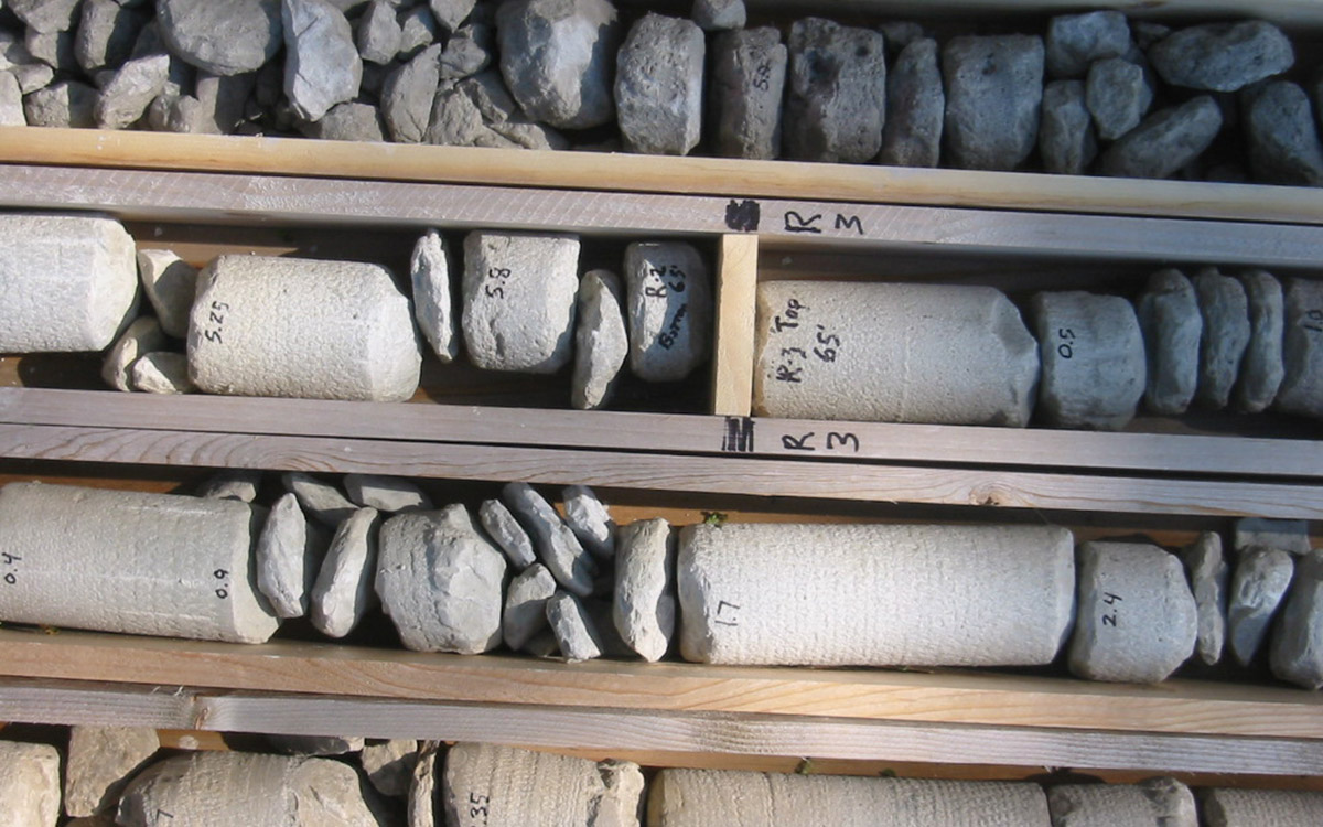
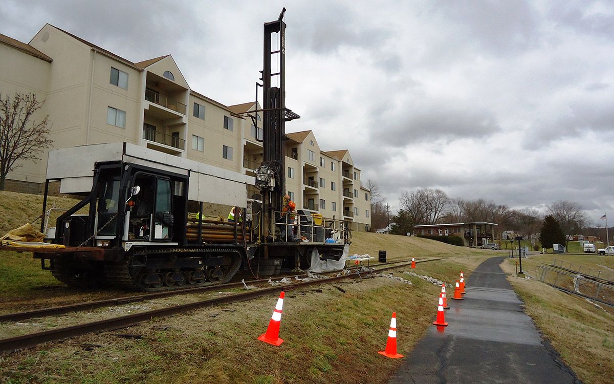
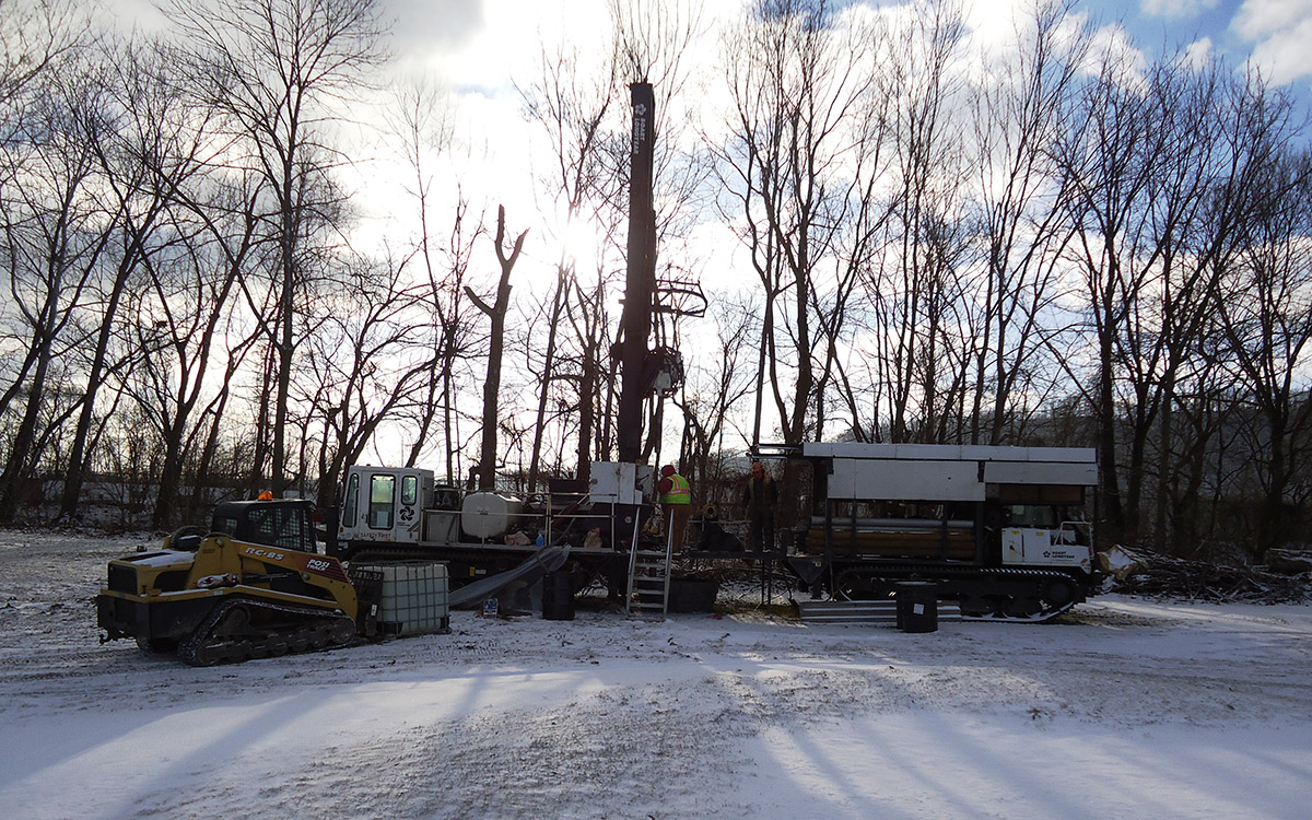
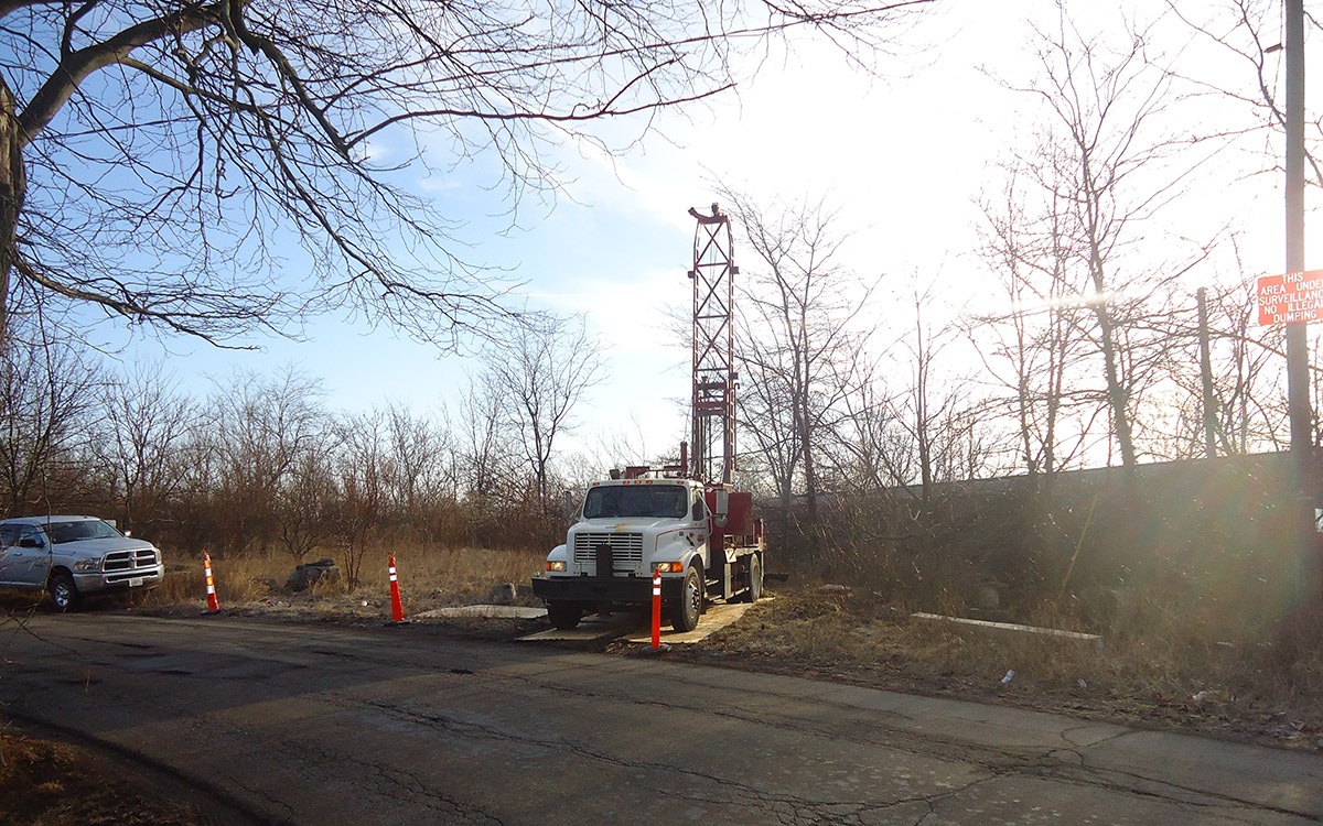
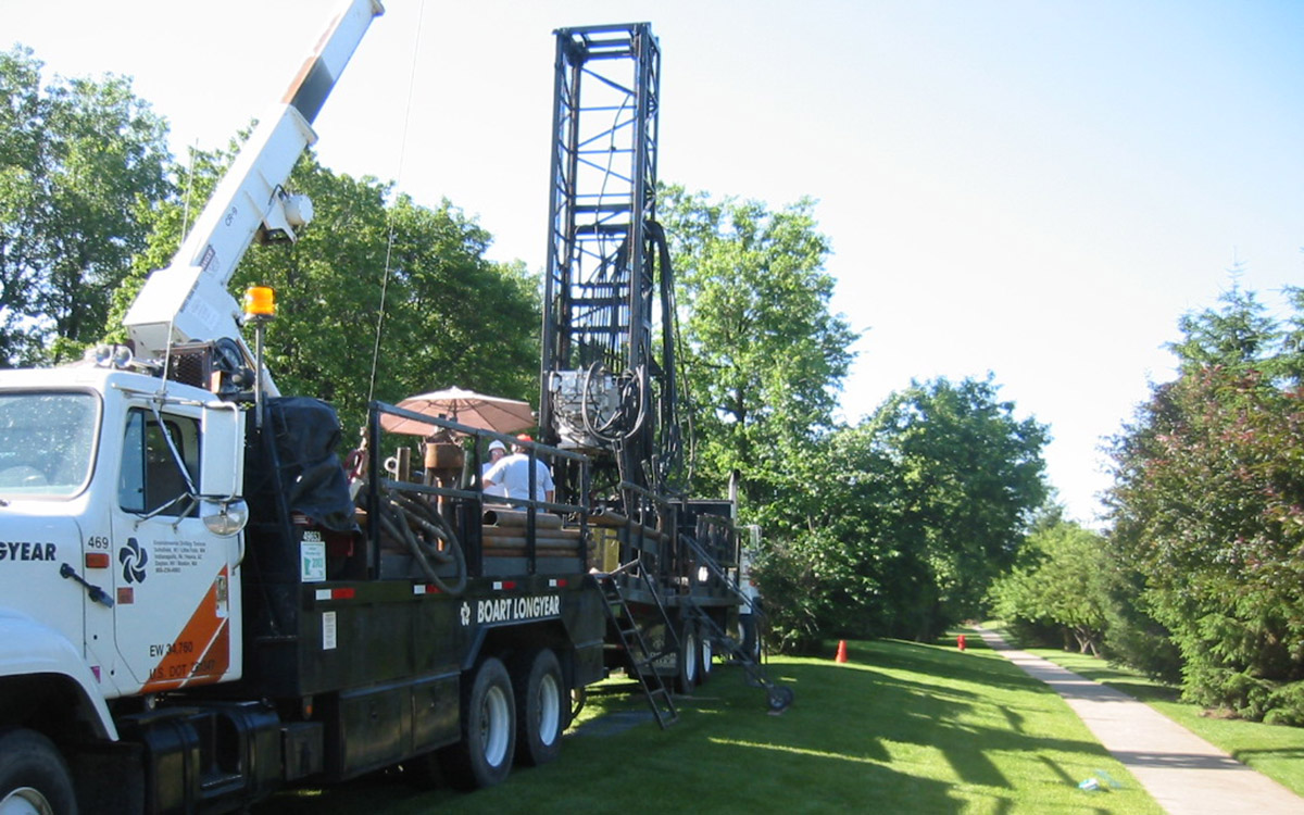
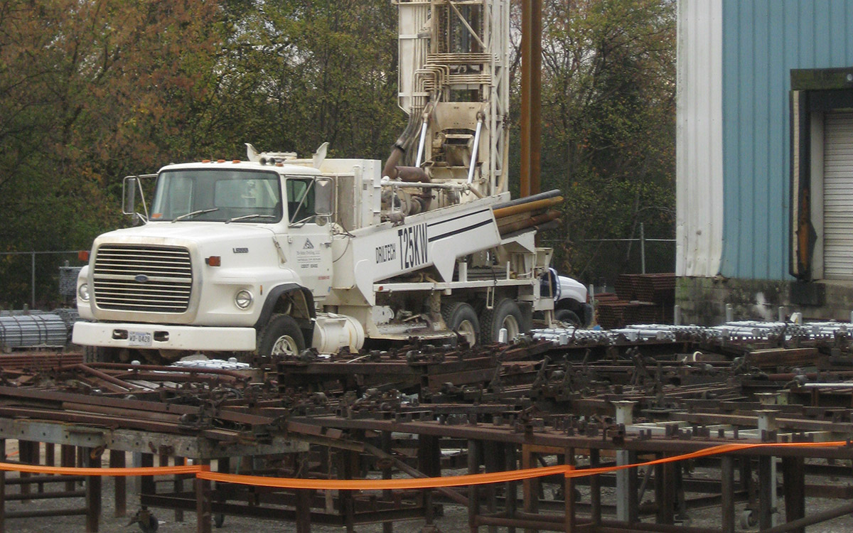
Rock core sampling is utilized to determine the physical and chemical nature of rock. Bedrock is usually encountered under soil overburden that varies widely in thickness. The overburden is typically sampled using a hydraulic push method until bedrock is encountered. Drilling techniques are then changed in order to sample the bedrock using a coring bit to collect a continuous rock core, or an air/mud rotary bit that brings rock chips to the surface for sampling. Rock cores are analyzed in the field by Geologist/Environmental Scientists to examine the core sample with respect to rock type, color, composition, bedding, structure, hardness, porosity, degree of weathering, and determine the rock quality designation (RQD).
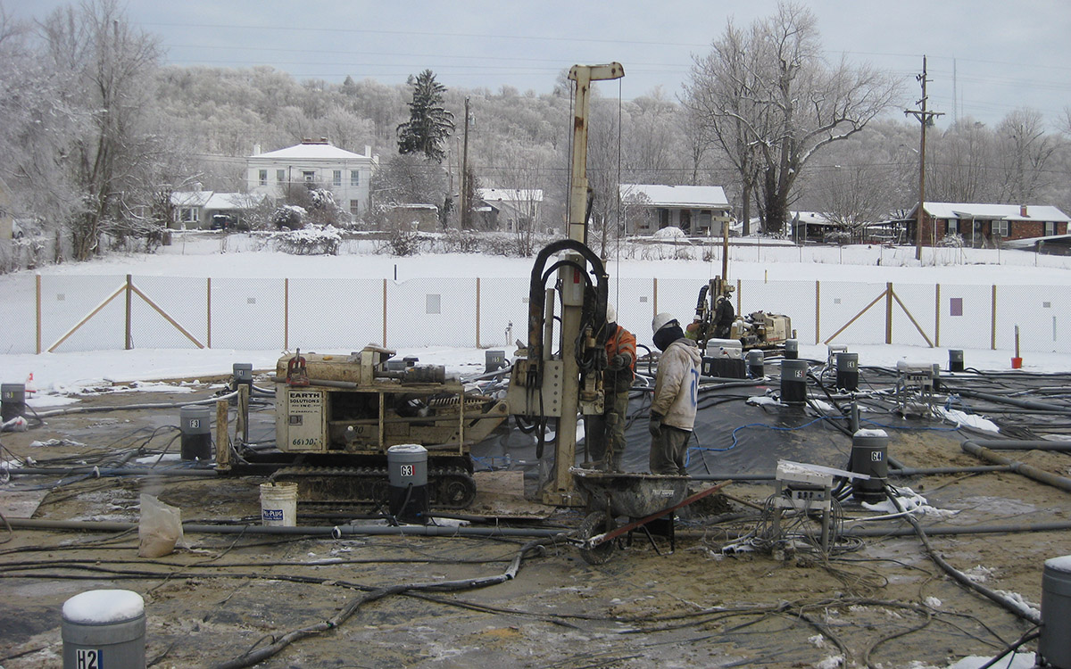
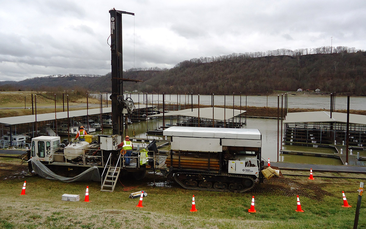
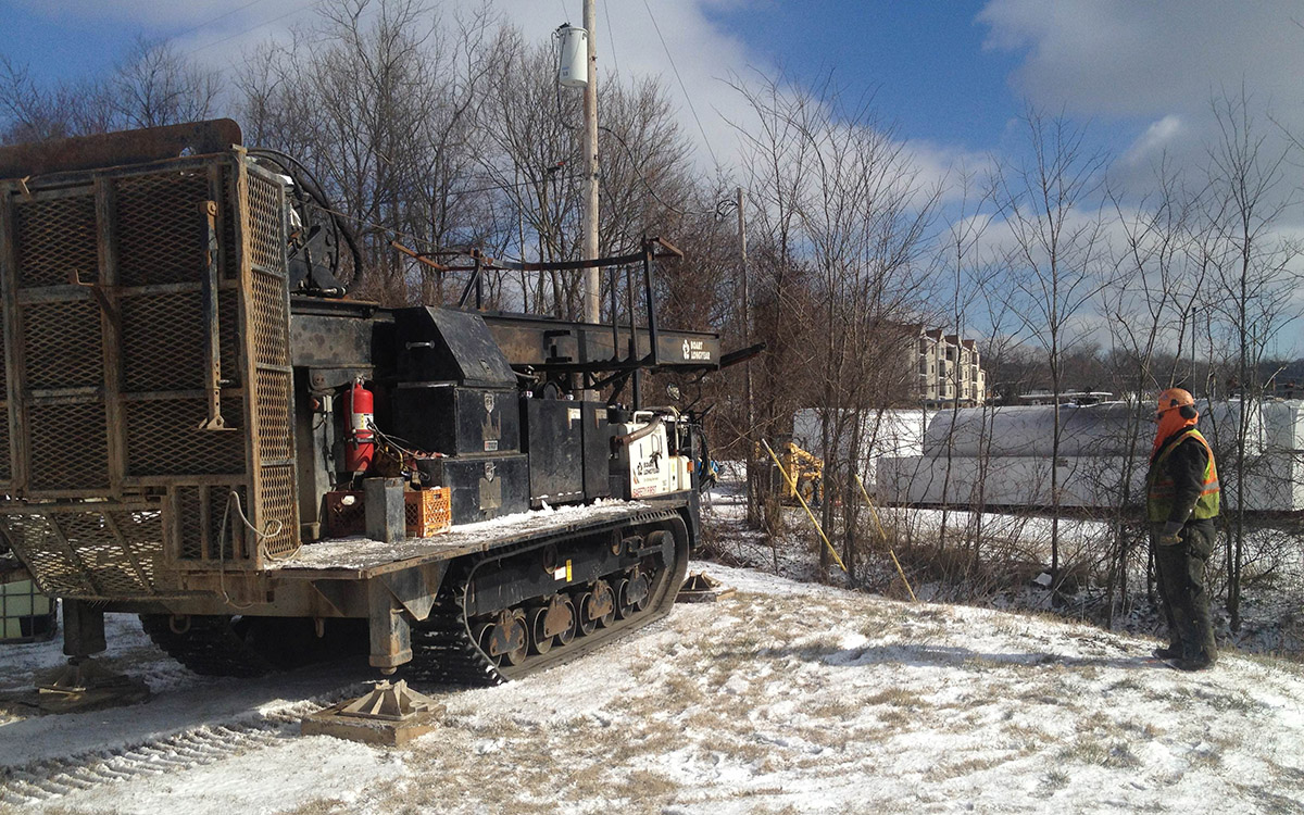
Groundwater monitoring wells are typically drilled using Hollow Stem Auger or Rotosonic Technology. The wells are installed to depths ranging from a few feet to over one hundred and can be utilized as one or any combination of an analytical sampling well, pumping well, aquifer transmissivity well, injection well, vacuum well, or groundwater elevation well.
The data from these wells can be used to generate groundwater elevation maps to show groundwater flow directions, plume movement of contamination, effects of the aquifer in conjunction with river stage elevations, as well as 2D and 3D renderings of the sites groundwater information.
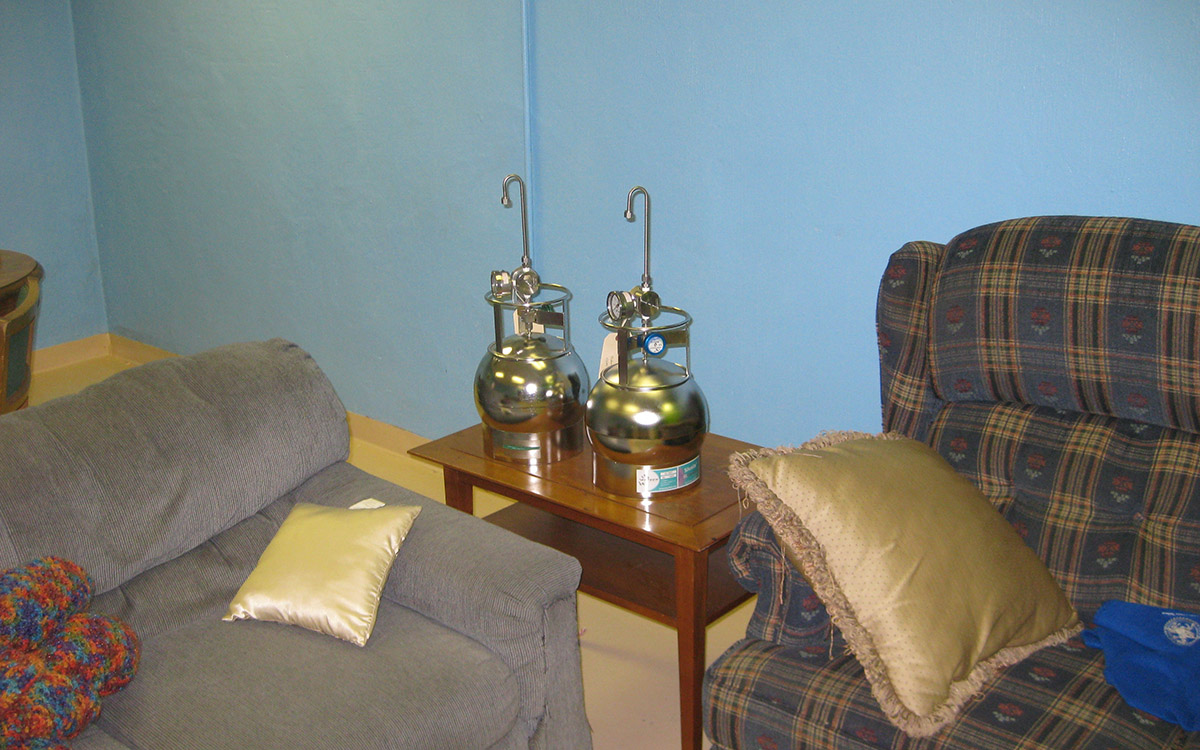
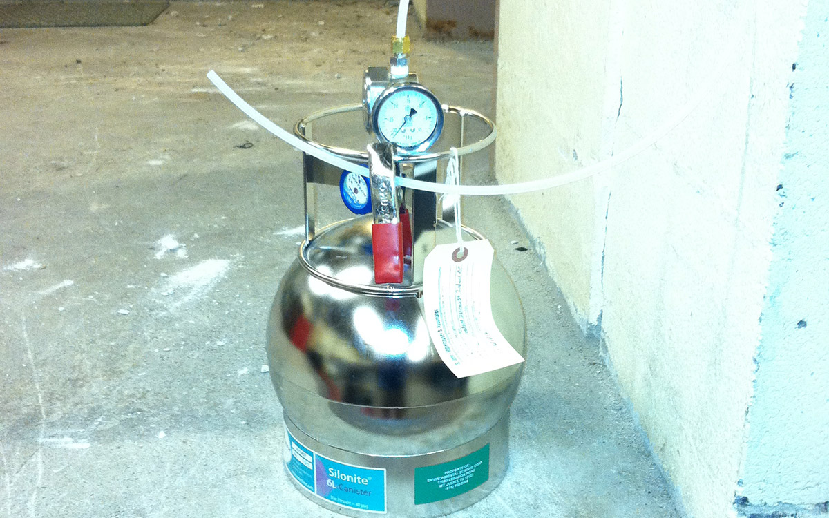
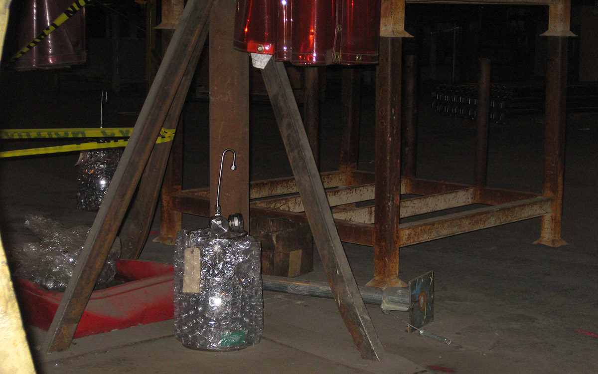
Vapor intrusion occurs when vapor-forming chemicals migrate from a subsurface source into an interior of a structure. A detailed indoor air assessment is completed for a structure prior to sampling to identify any activities or items that can interfere with the sample results. Utilizing specialized vacuum canisters, air can be analyzed to determine concentrations of chemicals present in the soil beneath a structure, directly beneath the concrete slab of a structure, or any part of the breathable air zone in a structure.
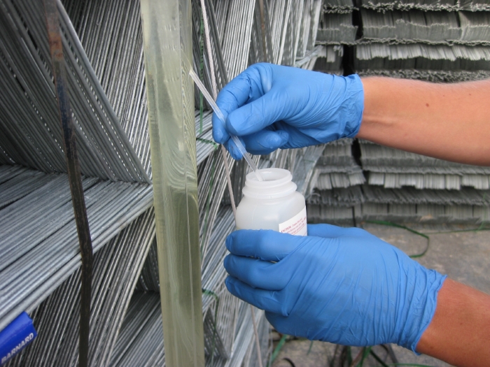
Hydrasleeves are small, disposable groundwater sampling devices that are placed within monitoring wells until sample collection. Hydrasleeves (pictured below) allow for rapid groundwater sample collection with minimal purge water generation. SMA favors Hydrasleeve sampling over traditional purge and sample or low-flow techniques in order to save money for our clients. This sampling method has been approved by some state regulatory agencies at sites requiring routine groundwater monitoring.
In order to effectively remediate soil, vapor, and groundwater contamination in the subsurface, both the magnitude and extent of the contamination must be determined. Most importantly, the source areas of the contamination have to be well defined in order to successfully remediate the site. SMA has decades of experience delineating subsurface contamination in a variety of geologic settings, using various types of drilling methods and sampling techniques. The animation below shows a 3D visualization of trichloroethylene (TCE) contamination in the subsurface soil.
Cone Penetration Testing (CPT) is a drilling method used to determine the geotechnical properties of subsurface soils. It involves advancing a specialized probe into the subsurface using a hydraulic powered drill rig. The probe is equipped with sensors that collect real-time data at regular intervals about the geophysical properties of the soil. This data can be modeled in 3D to show details regarding the subsurface geology, including the textural and permeability variations in high definition (as shown in the animation below). This information can be useful for both engineers (for construction applications) and geologists (for determining migration pathways of soil and groundwater contaminants).
• Site Characterization
• Hydropunch™ Sampling
• In-Situ Bioremediation Screening and Analysis
• Monitored Natural Attenuation
• Aquifer Testing and Analysis
• LNAPL Transmissivity Testing and Analysis
• NPDES Sampling
• Landfill Gas Sampling and Monitoring